

The motor position bolt at the rear of the motor on the internal framework holds the motor in the correct position in relation to the drive wheel. It is factory set and almost never needs adjustment. Almost never. I have come across a couple of new wheels that have been dropped at some stage, generally in transit, and the bottom plate of the motor cradle bends inwards a bit and changes the effect of the position bolt. If you buy a new wheel and the wheel head can be easily stopped with a bit of pressure then this could be the culprit.
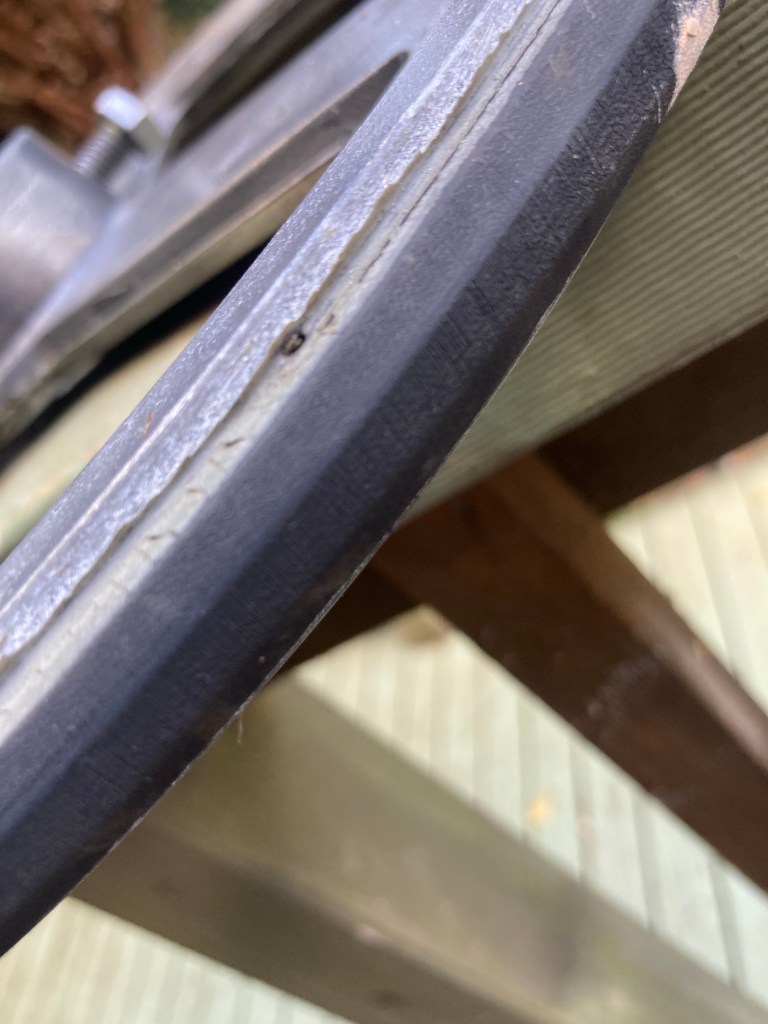
If the bolt is turned too far out then the point of the cone on the motor shaft will make contact with the metal edge of the drive wheel and make a loud metal on metal grinding noise. See photo below.

If the bolt is turned too fat in the cone will only make light contact with the drive wheel and the wheel head will seem easy to stop, particularly when centering. The correct pressure between cone and drive wheel rubber is also controlled by the small spring attached to the bottom of the motor frame. If this spring is missing or old and lost its tension then this can also cause the wheel head to slip when you’re trying to center clay. A third reason for slippage can also be that the cone has come loose on the end of the motor shaft. These things should be checked before considering adjusting the position bolt. See photo below. I have exaggerated the amount of distance between the cone and drive wheel. In reality it would still be touching but contact would be too light.

The reasons why you may need to adjust is when you replace a drive wheel and the diameter of the new wheel is different. It may only be a couple of millimeters but it can cause problems. The new drive wheels coming from the factory no longer have a chamfer on the side which also makes them prone to problems. See photo below

You will also have the problems of grinding noise or weak wheel head if the grommets are missing. Wheels have on occasion come in for servicing where folks have adjusted the bolt to try and eliminate the problem caused by missing grommets.
The amount of adjustment required is very small, generally only one turn of the bolt at a time. You go about it by loosening the lock nut and then turning the bolt one turn either clockwise or anti clockwise depending on your problem. The position of the bolt is a real pain in the arse to get to so lucky it doesn’t need doing that often. Best to do one turn at a time and then check the setting. Clockwise turns the bolt into the back of the motor and pushes the drive cone away from the wheel head. This is done when you are getting the grinding noise. Counter clockwise wives the bolt away from the back of the motor and pushes the cone in towards the drive wheel. This is done when the wheel head is easy to stop. A little amateurish video will try and give you an idea of how to do it.
How to adjust the motor position bolt to remedy the problem of wheelhead stops moving when centering pressure is applied.
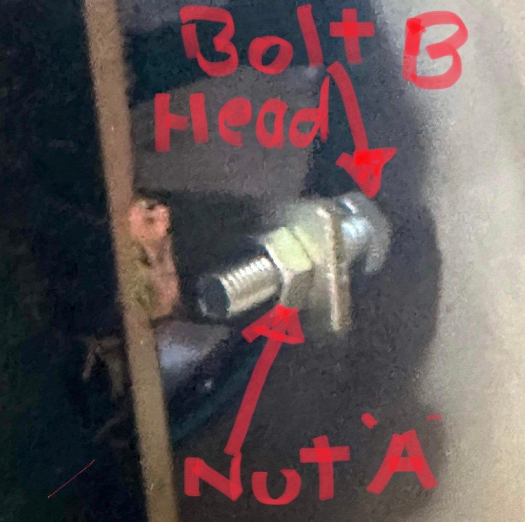
You will need 2 spanners and a texta marker. First make a mark on the bolt below nut A. This is so you can return it to the original factory set position if needed. 2. While holding the bolt head B in place with a spanner or multigrips, turn the nut A in a clockwise direction about 1/2 a turn. 3. Take a spanner and turn bolt head B in an anti-clockwise direction about half a turn. Don’t hold the nut A when doing this bit. Now turn the wheel over and see if it’s any better. If not try another 1/2 turn. Keep going until the problem is solved. If you make too many turns the cone might start hitting the metal part of the drive wheel. You will know if this happens because it will make an awful grinding noise. If this happens then turn the nut back in the opposite direction until grinding noise stops. Once you have it in the right position and the problem solved then you need to tighten the bolt in the new position. To do this once again clamp bolt head B in position and turn the nut A until it is tight.


Leave a comment