If you’re looking for posts on repairing pottery wheels click the link below
https://vencopotterywheels.wordpress.com/author/hugostiegl/
TABLE OF CONTENTS
- 1970-1980
- 1980-2000
- 2000- 2018
- End of an era.
- Information on repairs, adjustments and maintenance of Venco wheels.
- Some information about motors.
- Replacing missing grommets.
- Dealing with wheel noises and remedies.
- Motor mounting and fine adjustment.
- Springs and things.
- External links and information on other wheel brands.
- Contact and About Us
1970-1980
Early days in Melbourne.

This photo of an early prototype No1 and the pic below were pinched fro Two Muddy Men site.

No2 bench top portable wheel.
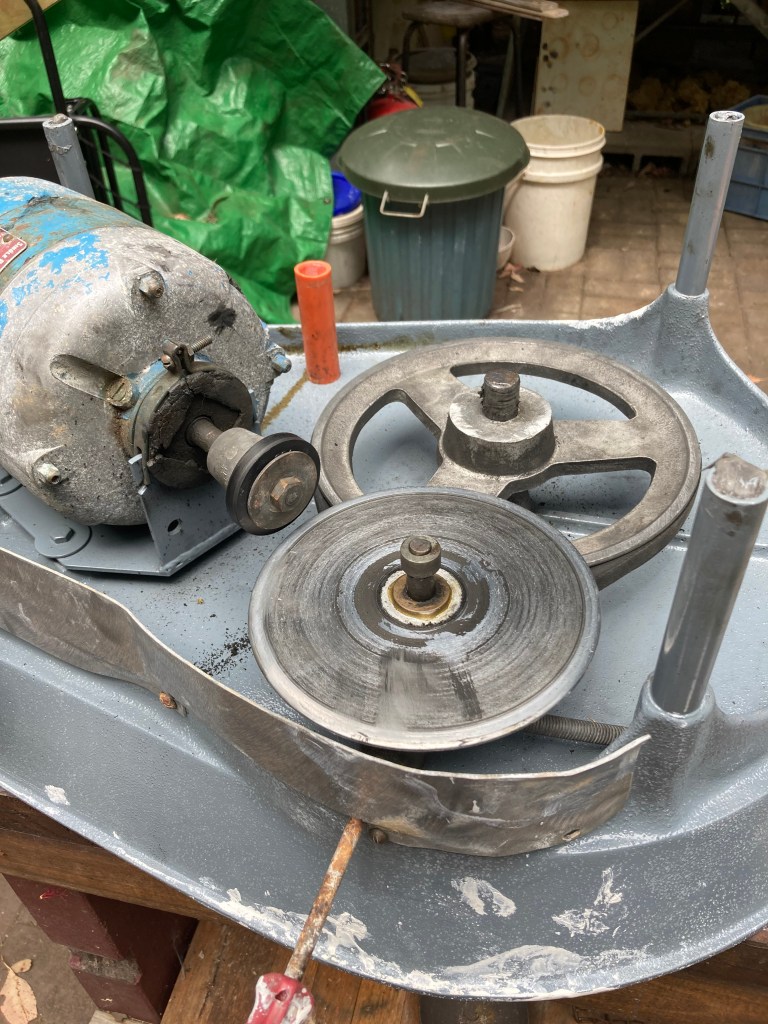
This picture shows the drive mechanism and speed adjustment lever of the early No2.. It originally had a notched piece of metal for locking the speed adjuster into place.

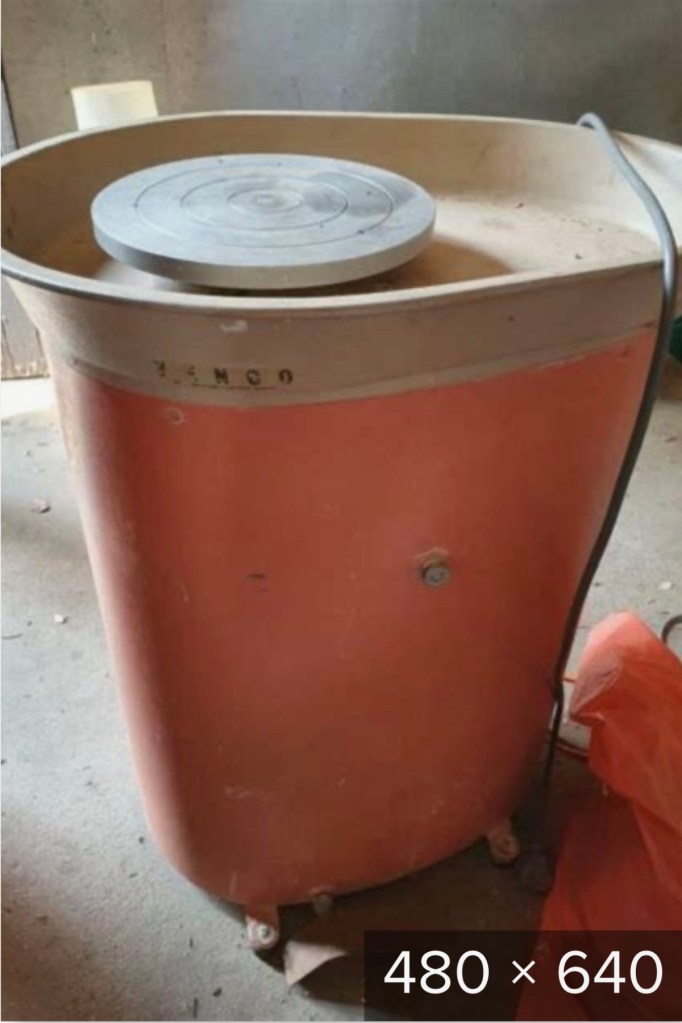
Another photo nicked from Two Muddy Men. Later version of the No2 wheel in salmon pink.
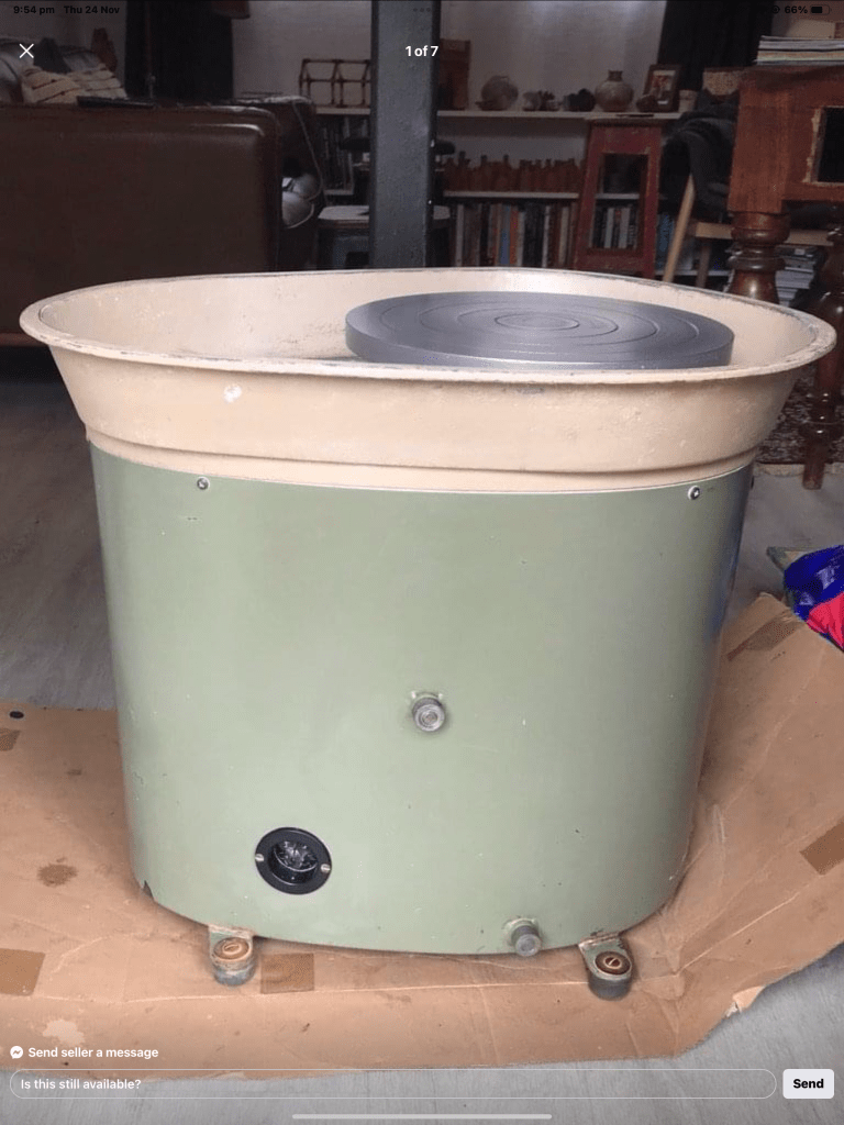
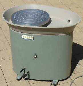
The most common of the Venco products is the No3 wheel. A standard in many TAFE colleges and university ceramics departments.
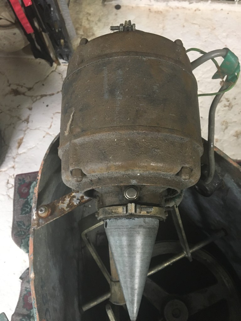
Busch motor in early 70’s No3

Very early No3 style, made in Melbourne prior to Geoff moving to W.A. Has a Busch brand motor with caps for oiling the bearings. No drainage hole in the tray.
Venco began its manufacturing days in Melbourne when Geoff Hill started to make pottery wheels in his factory. He was also producing wind turbines at the time. I don’t know a lot about his early years but I have come across references to a Venco kick wheel being produced at first. As more information comes to hand I will update this story.
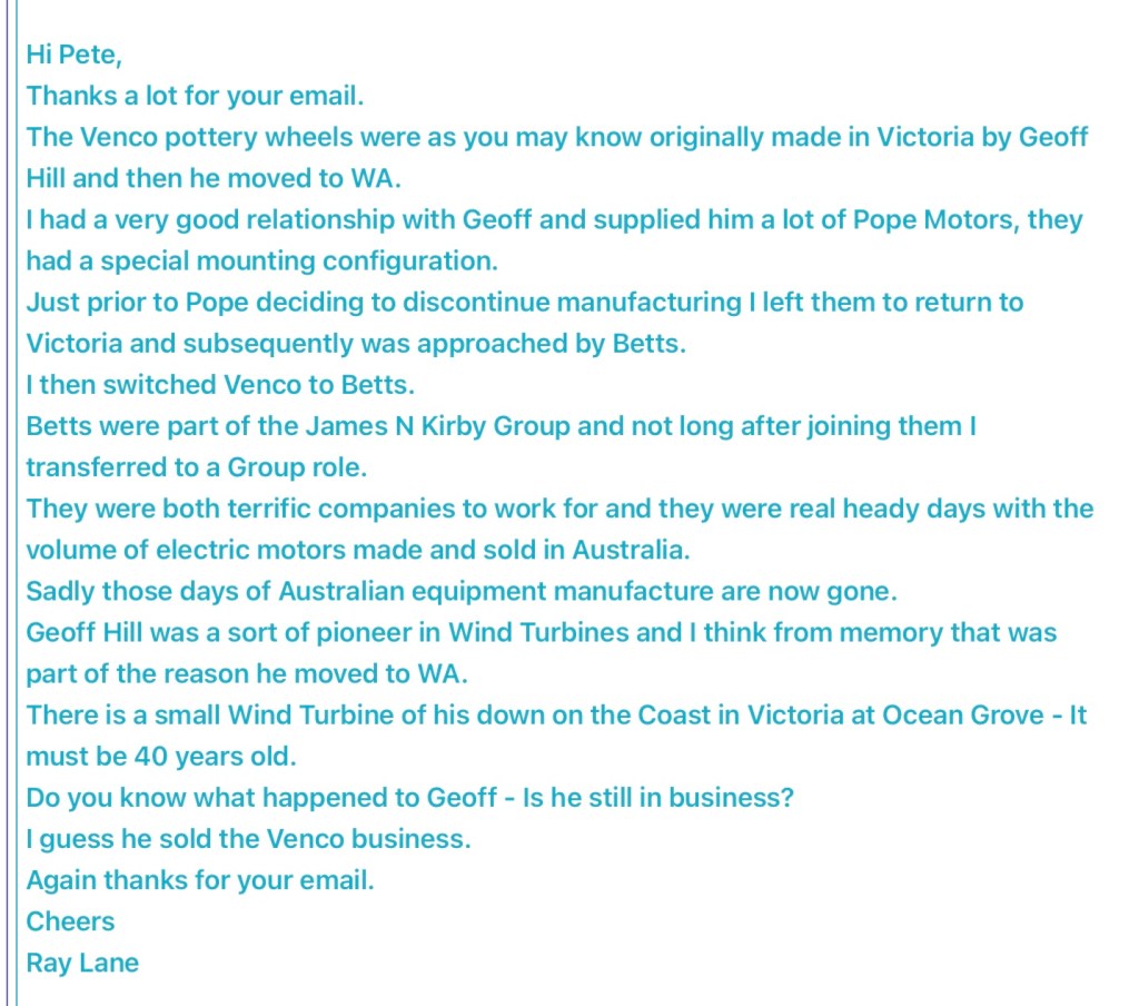
Here’s an email from Ray Lane who worked for Pope motors and later Betts motors.
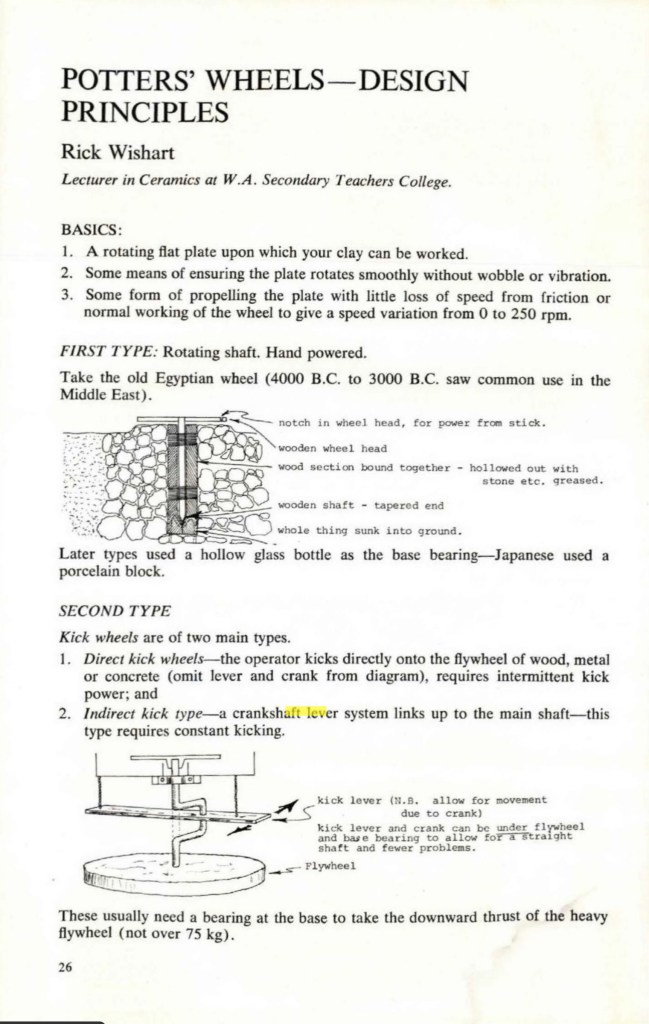
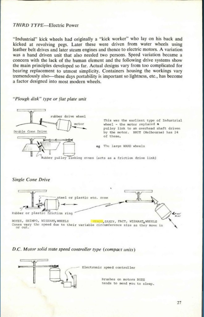
Below is an article about wheel drive technology from Pottery in Australia magazine.
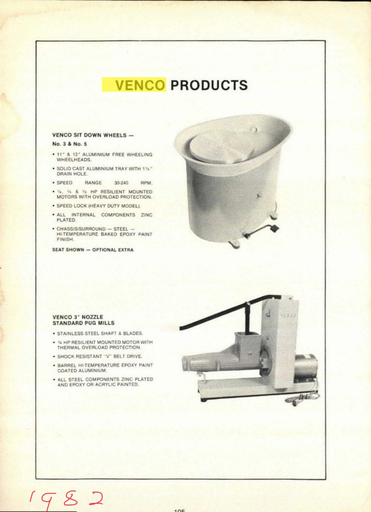
Some models of early Venco wheels are, No1, standup wheel, No2 benchtop wheel, No3, standard wheel, No5 heavy duty with speed lock.
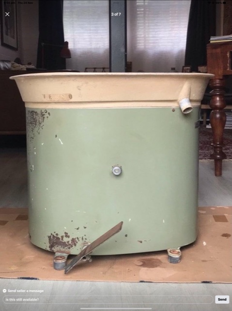
Several different colours were used in the 1970’s. A salmon pink, chocolate brown, and typical green. From what I can gather the brown was used for the No5 wheels.
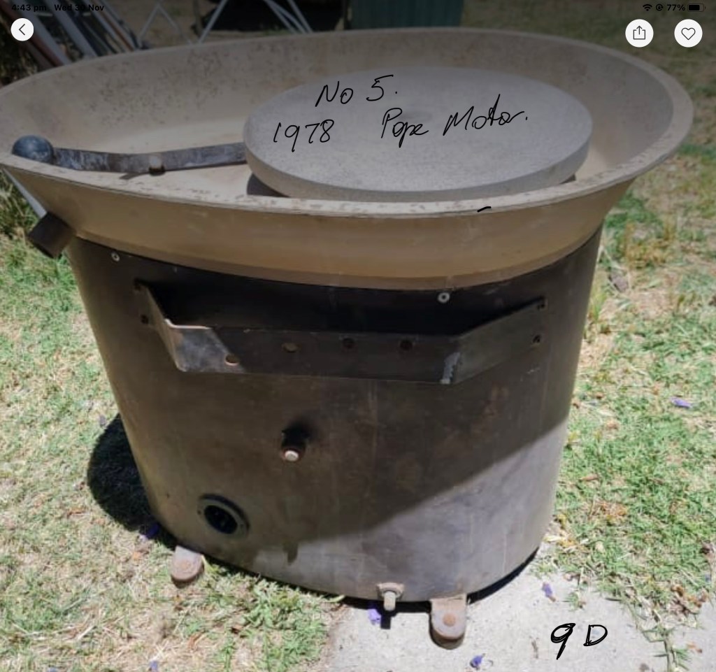
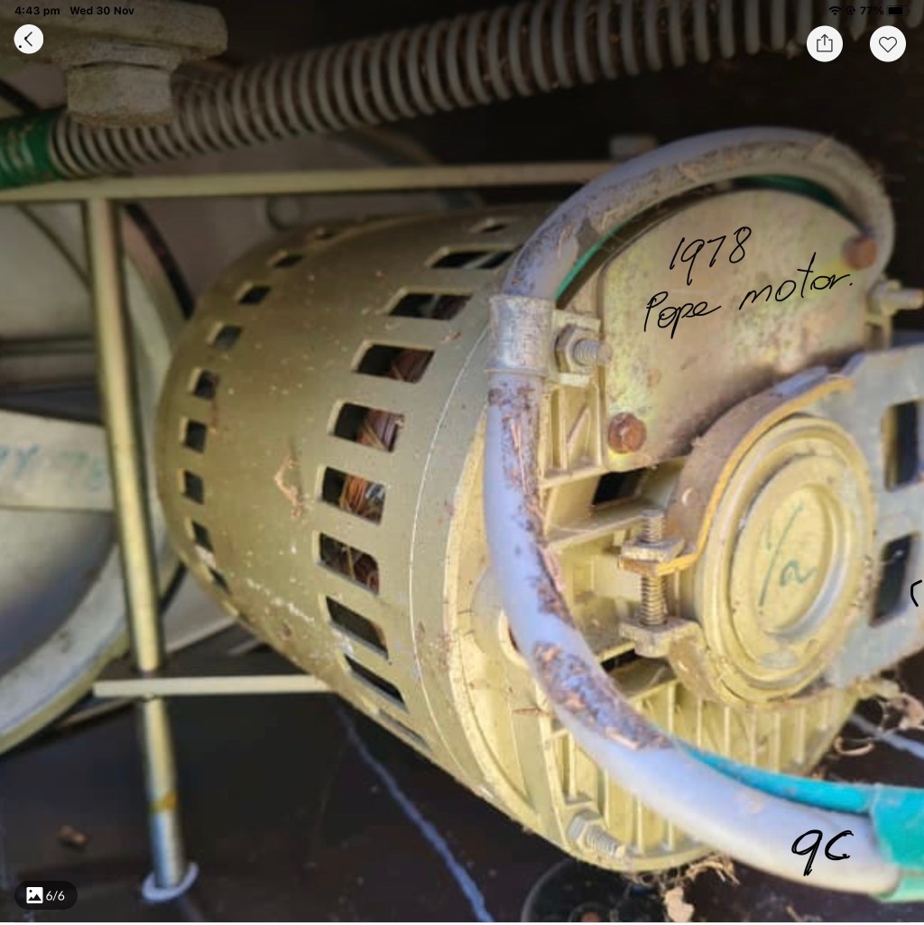
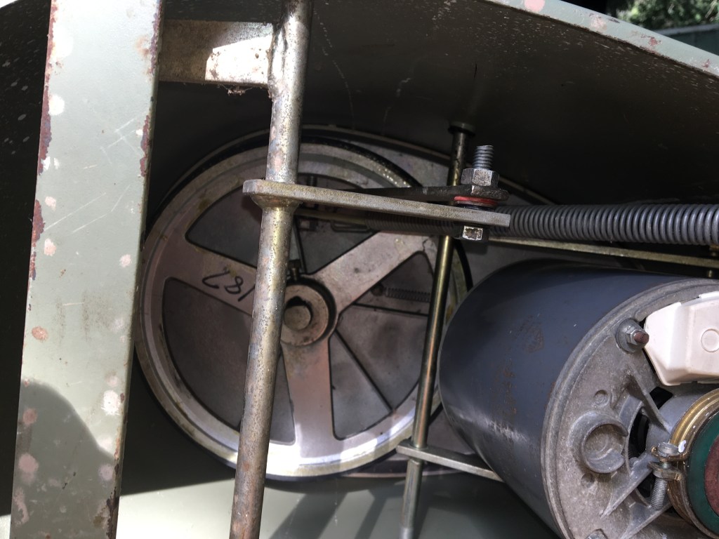
The first wheels had welded on lugs where the grommets go on the frame. These are a bugger to work with and take quite a bit of effort to insert. Sometime in the mid 1970’s this was changed to a pressed in hole for the grommets which made replacing a lot easier. The wheels came in three colours, salmon pink, green and for the No 5 heavy duty wheels, chocolate brown. While still manufacturing in Melbourne Geoff started to use Aus made Pope motors. The manufacture date of the drive wheels was written on the aluminum spoke in texta. This is the easiest way to date a wheel as long as the drive wheel has not been replaced.
A standup model from the early 70’s with welded on grommet lugs.You don’t come across many of these but still use the same drive wheels and motor etc.
1970’s wheel in very nice condition. The plug for the power chord was a characteristic of 70’s wheels and by 1980 was discontinued and the power chord went to the motor directly. Has the welded on lugs for grommets.
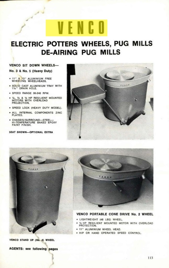
The first ad featuring pictures of Venco wheels in Pottery in Australia magazine.Volume 16 no 1. Features No 1 standup model, no 2 benchtop portable and no3 standard.
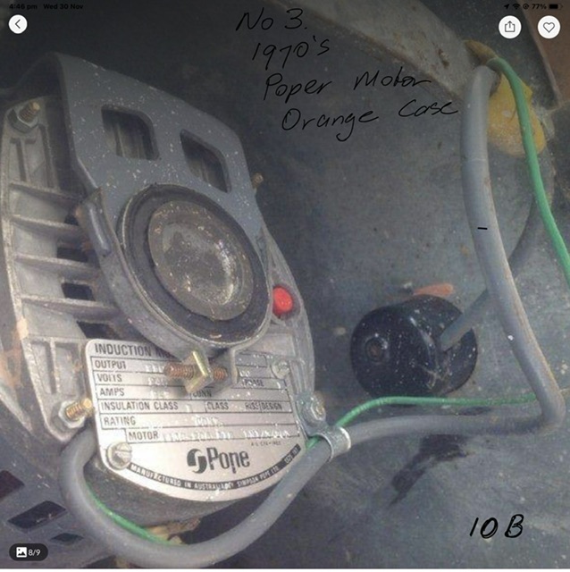
Pope motor with red overload button. The later motors don’t have this feature. It was a bit of a trap if you didn’t know it was there and you could have thought your motor had carked it when it was only the overload switch.
The 1/4 hp compact wheel, often dubbed K9 from the BBC Doctor Who series with Tom Baker. Made up until the mid 1990’s. These wheels use 8 small grommets rather than the 4 x small and 4 x large that the now’s use. Also they have a smaller drive wheel that are no longer available. The last ones I came across were at “The Pugmill “ retail supply store in S.A. When purchasing one of these you should check the condition of the drive wheel first as getting a replacement can be difficult. There is an alternative and I have been experimenting with a way of reconditioning drive wheels using polyurethane glue. So far they seem to be working great. Time will tell and I have put some reconditioned drives in some of the hire wheels I am renting out to students.
This picture shows the type of foot pedal used in 70’s wheels.
1980-2000
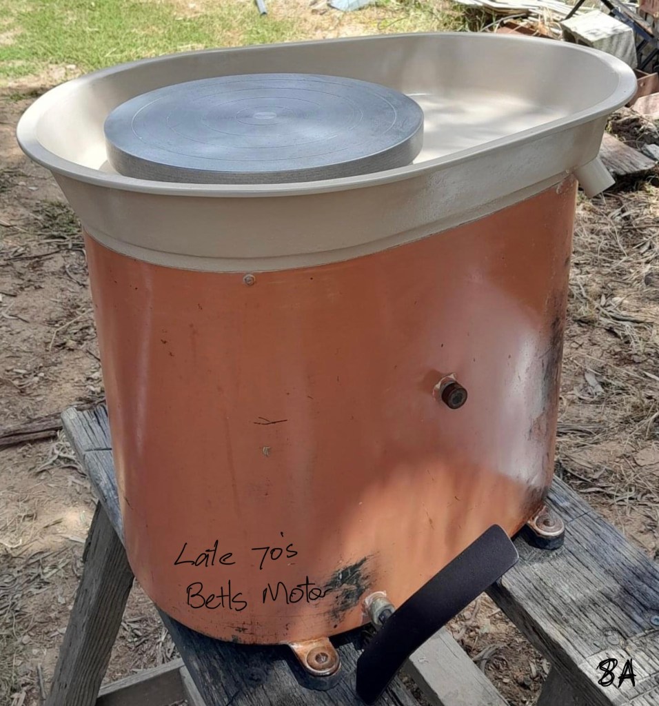
Some of the changes that happened around 1980 were (a) the foot pedal changed to the bent metal rod with small square metal pad. (b) the plug on the side was discontinued. (c) changed from Pope motors to Betts motors. The Betts motors were used for many years before they became Brook Crompton Betts in the mid 90’s. Later motor brands used were Crompton Parkinson and Fasco.
New style of foot pedal introduced around the end of the 1970’s. 13” wheel head. There were a few variations of the no3 wheel around the 1980’s. The typical one shown here with 13” wheelhead and 1/2 hp (370 watt) motor. A cheaper alternative had an 11” wheelhead and 1/3 horsepower motor.
Ad from Pottery in Australia 1982 showing wheel with new design foot pedal. I purchased a new Venco wheel from a retailer in Lismore around this time. The wheel is now in the studio of my friend Daniel In Bonnells Bay.
1987 model with grey Betts motor.Date can be seen on the drive wheel.(87)

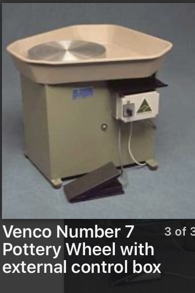
The first of the Venco electronic wheels was introduced sometime in 1999. I am not sure of the exact date but will update when I know. I haven’t had a lot of experience with these as not many were made. They were very popular with potters making large work. Some of the big blokes like Bill Powell have a lot of good things to say about them. Had a DC motor,possibly 3/4 hp or more, and electronic controller and a potentiometer in the foot pedal. Anyone familiar with American Brent wheels will know the setup.
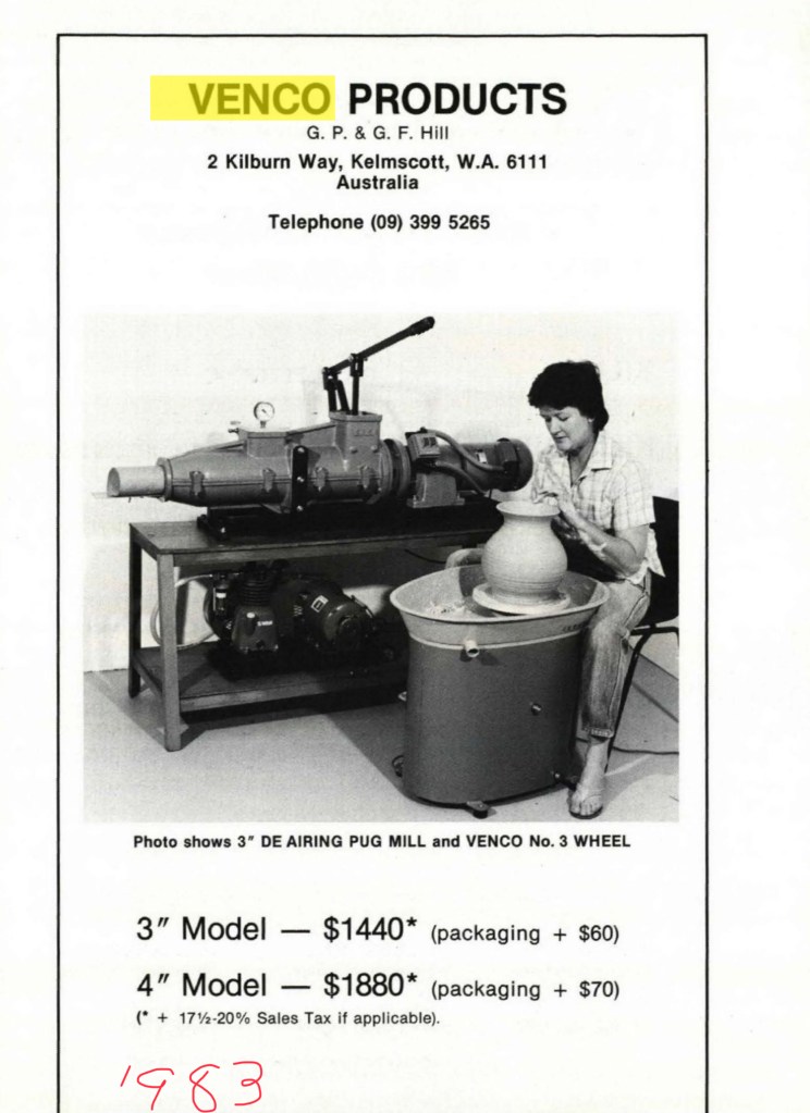
Another Venco ad from 1983.
2000- 2018

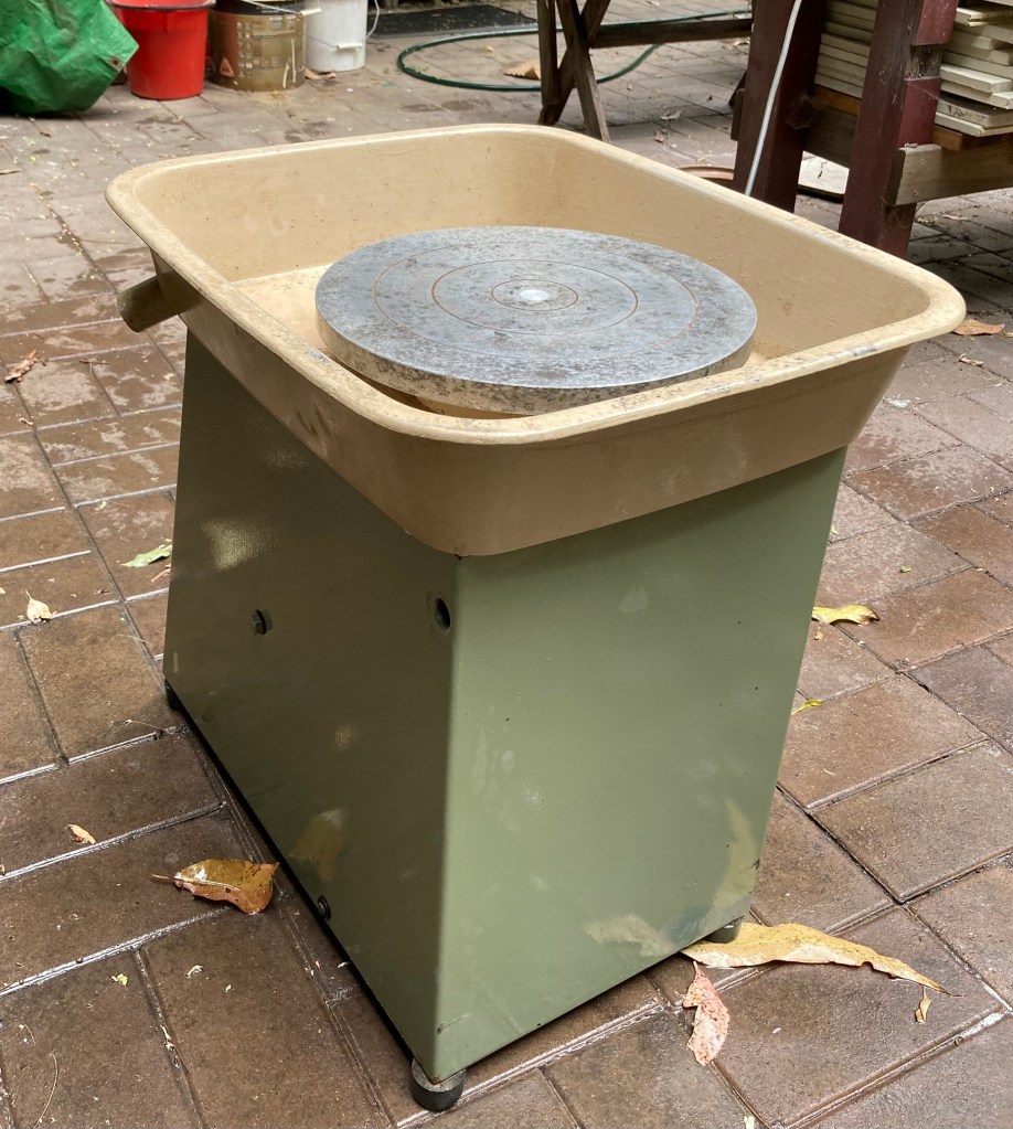
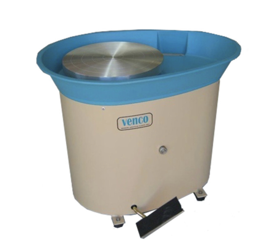
The first major change to the design of the splash pan happened around 2000 when the round drainage hole was replaced with a rectangular one with a small stainless steel sluice plate. The exact reason for this change is unknown to me but what I heard was this. A lot of people including myself were in the habit of blocking the hole with a bit of clay to avoid having to use a bucket to catch slops that never seemed to get into the bucket. Also bucket tended to get in the way. Blocking the hole however, has caused other problems including the fact that doing it apparently voids the warranty. Under the wheel head is another small drain hole , the purpose of which is to prevent clay slops from getting into the bearing sleeve. The position of the hole is underneath the drive wheel and when slops hits the drive wheel it sprays all around and can cause damage to the motor if it gets covered in slops. You can see it if you tip your wheel over. Anyway the new design drain was supposed to make it harder to block up but unfortunately this design of drain was worse than the original and clay just seems to go everywhere but the bucket. There is someone producing a 3d printed attachment that directs the slops into a bucket. I think Walkers may be selling them.
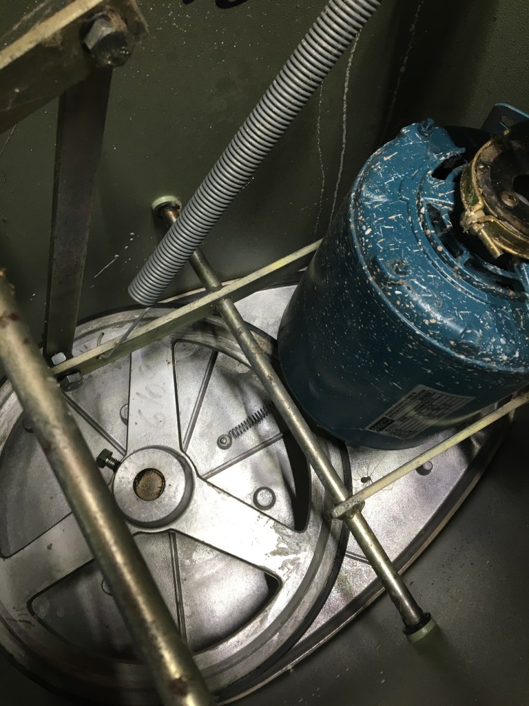
Fasco brand motor in a 2008 wheel
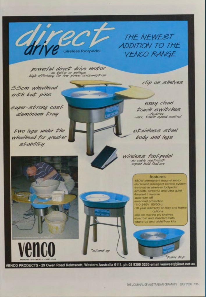
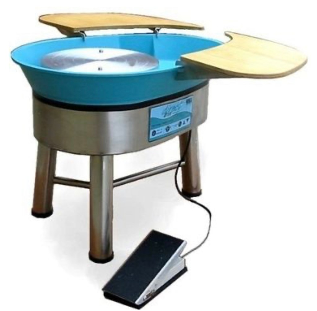
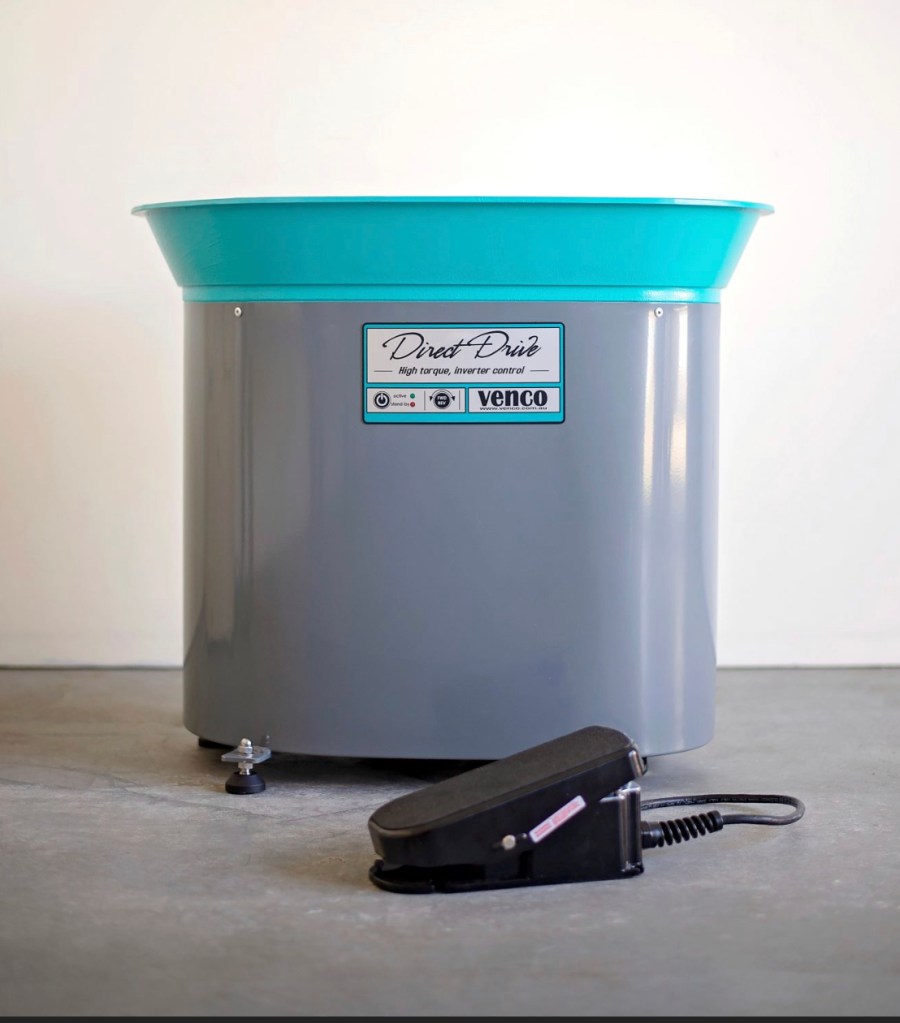
First advert in Journal of Australian Ceramics mag 2006 for new direct drive. Had a wireless foot pedal which was discontinued shortly afterwards. The Direct Drive wheel uses a planetary motor similar to the new style of washing machines. I believe it is actually a Fisher and Paykel washing machine motor made in NZ but maybe that’s just hearsay.

End of an era.
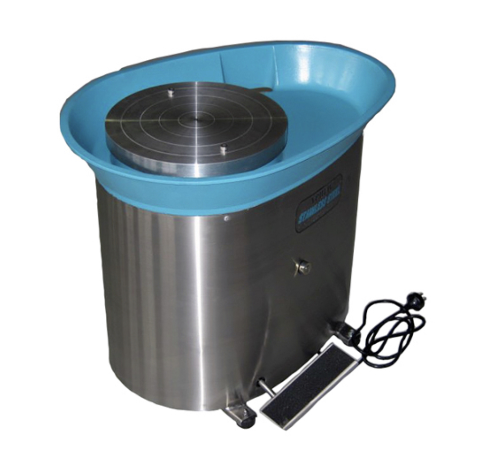
Sadly, Geoff Hill passed away after a short illness in 2018. The company continued to operate but was in limbo for a couple of years while a new owner was sought. Eventually Geoff’s grand son Elliot , who had done his apprenticeship at the Venco factory took over the company. Shortly after the ubiquitous No3 got a do over and became No3 Mark II. Some of the changes included, a new colour, sealed roller bearings in the wheel head and a change to the design of the internal linkages. A new brand of motor came into use replacing the existing Fasco motor. The new motor RCG brand for Royce Cross Group are made in India from what I understand. Unfortunately they are no match for the motors previously used that were Australian made. The decline of small manufacturing in Australia has led to the decline of a lot of locally made products. A stainless steel version of the No3 also became available. The Venco Direct Drive wheel also had a makeover looking much more like the No3 wheel.
Information on repairs, adjustments and maintenance of Venco wheels.
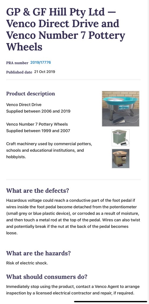
Not everything goes to plan. A recall for electronic wheels ,No 7’s and Direct Drives occurred in 2019 when a possible fault was discovered in the foot pedal.
Some stuff about drive wheels.
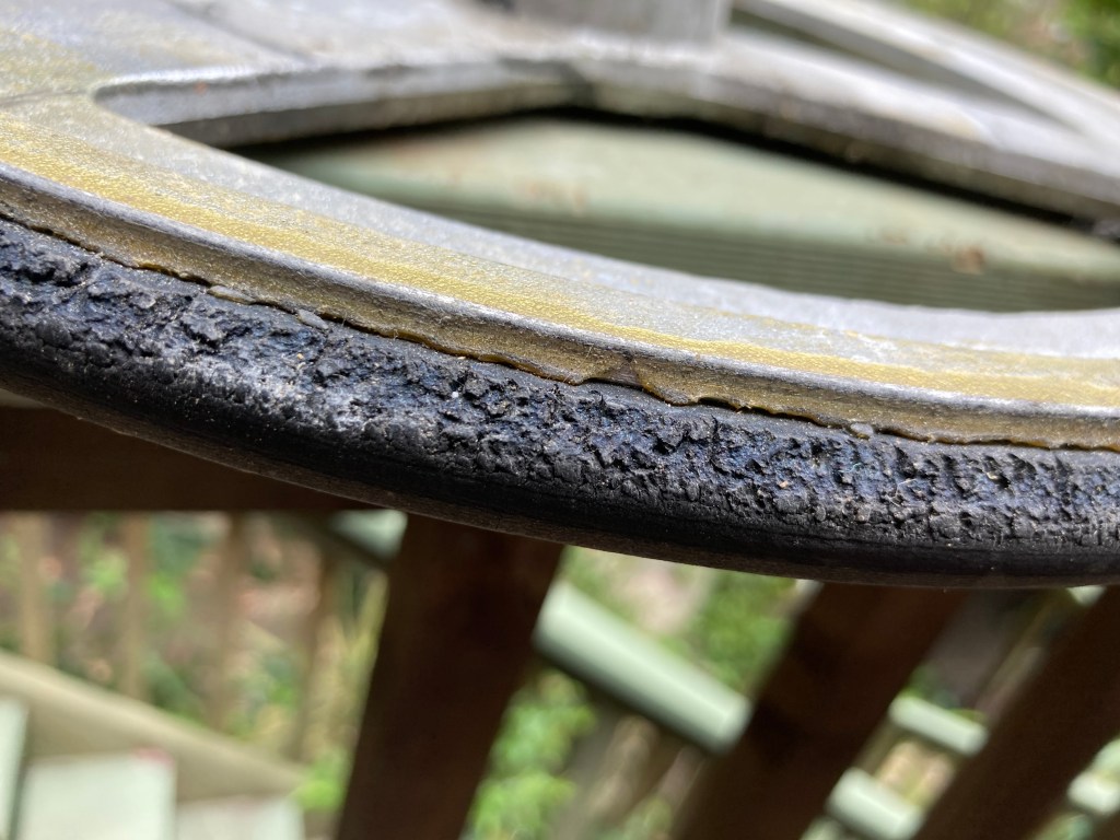
Two images showing a normal drive wheel (top pic) and a badly damaged one.(bottom photo) At the moment a new drive wheel will set you back around $250 plus installation if you choose not to do it yourself. It’s quite easy to do by the way. The main reason I see this sort of damage is because of missing grommets. You should never use a wheel that has missing grommets because it causes misalignment of the aluminum cone on the end of the motor shaft and it can dig into the rubber causing unrepairable damage. The drive wheels last between about 15 -30 years depending on usage and how the wheel is stored. I have seen some old models from the 80’s where the dive wheel is still usable but usually by this stage they start falling apart. The first sign of deterioration is small vertical cracks around the circumference of the wheel. If got to soon enough they can be reconditioned.
Some information about motors.
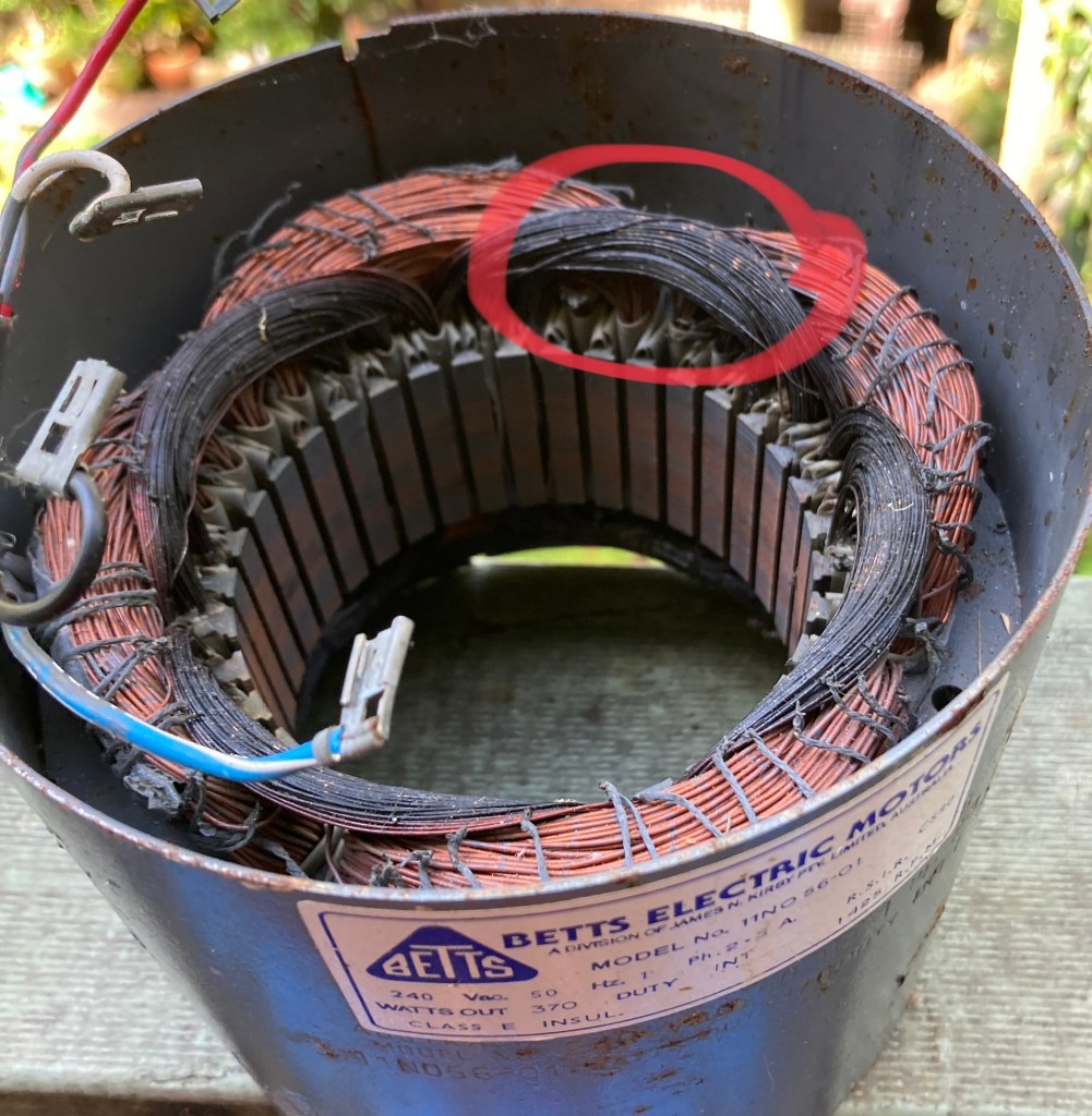
The motors used in Venco wheels up until recent times are Australian made and of very good quality. Betts motors are some of the best motors made worldwide. Nothing lasts forever though and there are a few things that can go wrong with your motor. These motors are what is called split phase with centrifugal switch. Basically the wiring inside the motor is split into a light gauge starter windings and a standard run winding.when the power is turned on the starter winding kicks in and this controls the direction of the motor clockwise or counter clockwise depending on setup. After a couple of seconds a centrifugal switch comes into play and cuts the start winding and switches over to the main winding. Because of dust, clay, insects and other crap that can get into your motor, it can cause the centrifugal switch to stick , either in the off position or on position. If it sticks in the on position the starter windings will quickly burn out causing a lot of smelly white smoke and a dead motor. Bad news , a new motor is needed, it’s not worth the cost of having them rewound. Not so bad if it sticks in the off position. This causes the wheel to start very slowly and may turn in either direction. If it is doing this the motor should be taken out and serviced as it can quickly change at any stage and get stuck in the on position and that magic white smoke escapes killing your motor. A motor rewind shop can do this for you and generally entails blowing out dust and crap and cleaning and lubricating the centrifugal switch. Another thing that can go wrong with a motor is bearings. If the motor is noisy when turned on but is not engaged with the drive wheel then your bearings need replacement. My local rewind guy charges about $100 to clean motor and change bearings. I keep a few reconditioned second hand motors in stock for repairs.
Replacing missing grommets.

Grommet on the outside of a wheel.
I won’t go into how to replace grommets as there is a very good video on how to do it made by Rob Linigen (https://www.robertlinigen.com/ ) at Nepean TAFE a few years ago.
Video on how to replace a grommet.
Dealing with wheel noises and remedies.
Wheelhead and sleeve bearings,
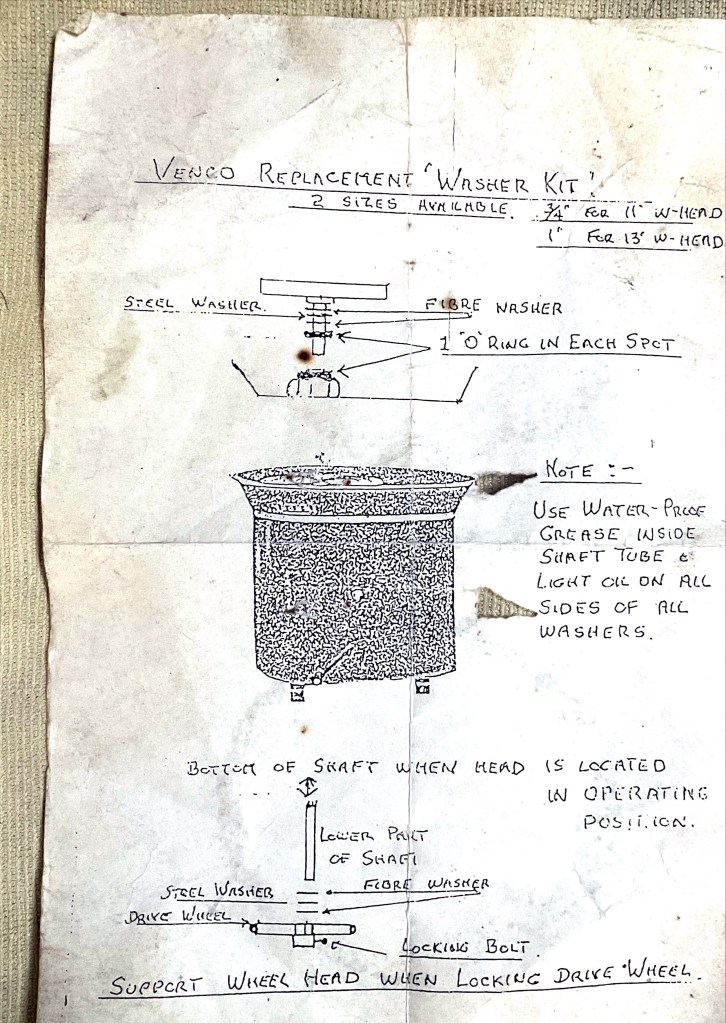
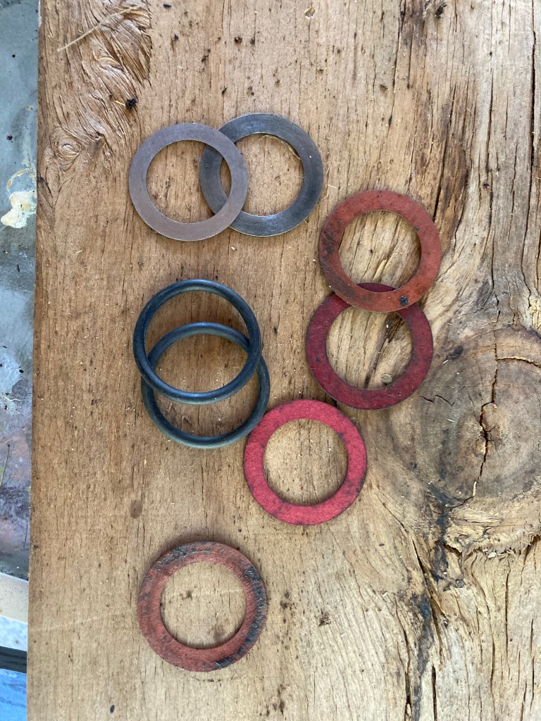
Diagram of how the wheelhead washers and o rings fit in.
Grinding and weird sounds coming from wheelhead. Try and turn your wheelhead with the motor turned off. It should rotate easily and have very little vertical play. Try pulling the wheelhead up, it should not move more than a couple of millimeters. If it is hard to turn or makes a scraping/grinding sound then some maintenance is required. To remove the wheelhead you need to tip the wheel over and remove drive wheel. Always support the motor when flipping the wheel so as not to cause damage to the drivewheel. If the end of the cone on the motor hits the drivewheel with force it can put a ding in it.
Undo the nut that hold the drivewheel to the shaft and wriggle it up until it comes off. When you turn the wheel back over the wheelhead should come straight out. Check around the top of the bearings and under wheelhead for any bits off stuff like old cutoff wire that may be stuck there. Clean off any lumps of caked on clay that might be causing a noise. Now check that all the ‘o’ rings, metal and fibre washers are in good condition. Refer to the above diagram for correct placement. These parts can be obtained from many suppliers such as Keanes or Walkers. Clean out old stiff grease and apply lots of new waterproof grease to all parts and re-assemble. When you flip the wheel over to replace the drivewheel you will need to put a block of wood or similar under the wheelhead to support it and prevent from slipping down. Check that the lower set of washers are in place and tighten the nut on the drivewheel. It is good to have a small amount of play, a couple of millimeters, between the end of the bearing housing and drivewheel so the wheel head is not too tight. The wheelhead should now turn freely with the motor off.
Brass sleeve bearings used in venco wheels prior to the introduction of the Mark II wheel . They are very long lasting, I have only ever had to replace one set of these over the years of repairing wheels
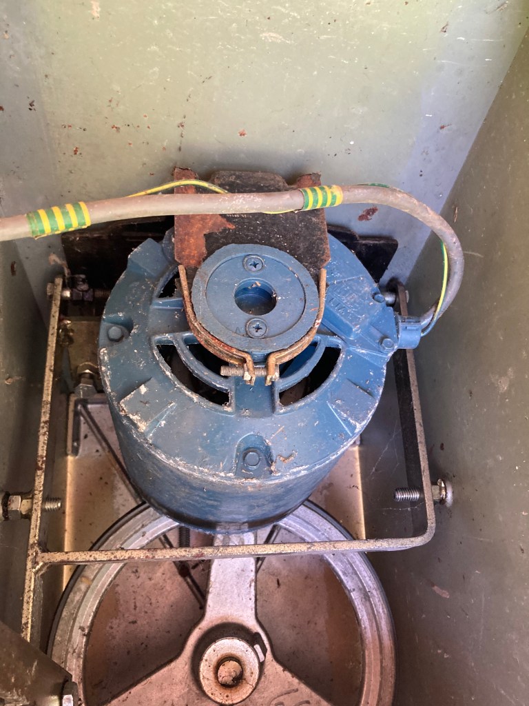
Motor mounting and fine adjustment.
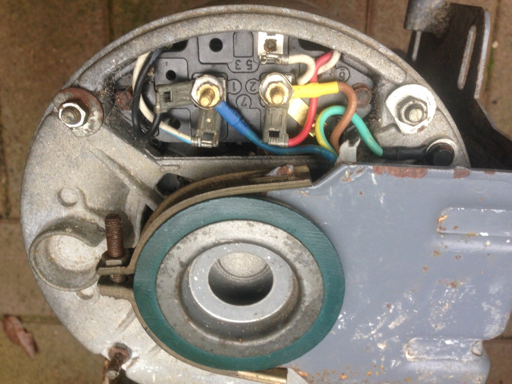
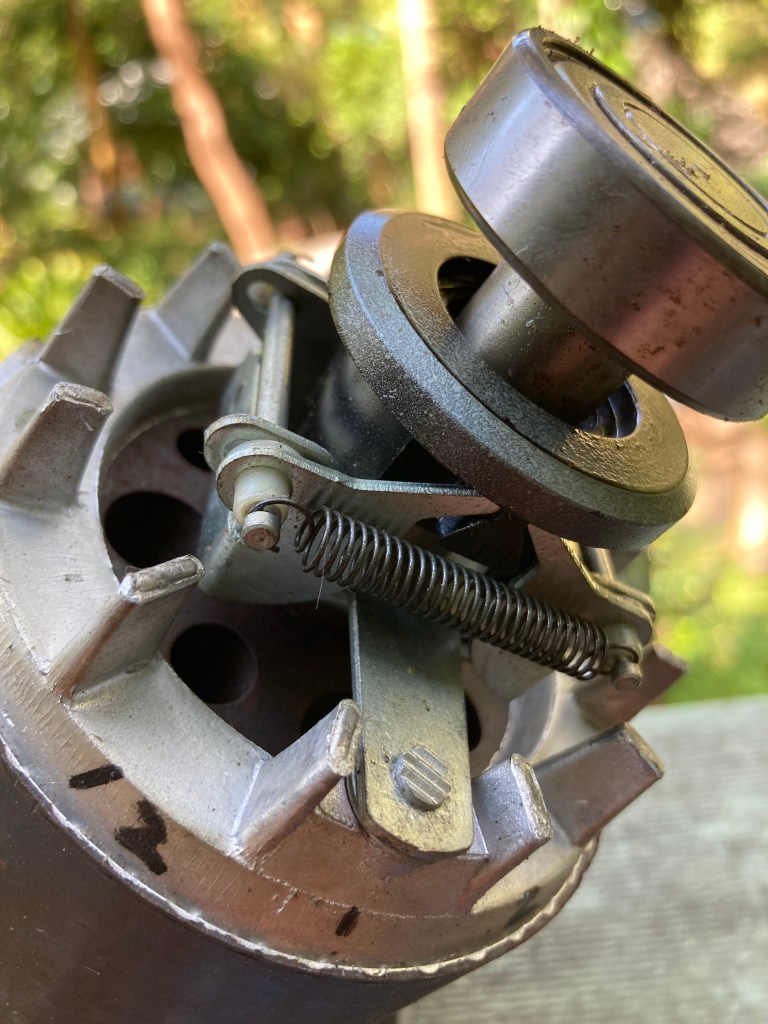
Sometimes problems may arise with loud grinding noise when the foot pedal is pushed and the motor cone engages with the drive wheel. The most common reason is missing grommets and the repairs needed was outlined previously. Another less common cause can me mis-alignment of the two fine adjustment mechanisms on the motor frame.

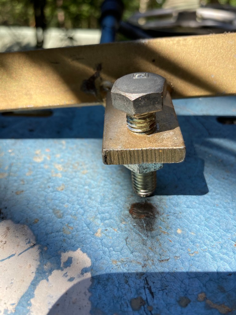
First I will deal with the set bolt at the rear of the motor. I spoke to Geoff Hill a few years back and he explained the reason for this bolt. He said it is factory preset and under normal circumstances , should not require any modifications. The bolts controls how and where the cone engages with the drivewheel rubber when it first touches it. If the cone is too far over the point of the cone will hit against the metal part of the drivewheel and produce an awful grinding noise. If it is too far the other way then the tip of the cone will not engage properly with the rubber and you get no slow speeds, or the wheelhead will stop with a small amount of pressure applied. Adjustment is very small amounts, half a turn at a time.
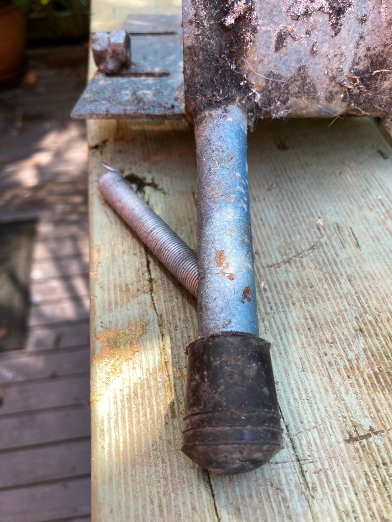
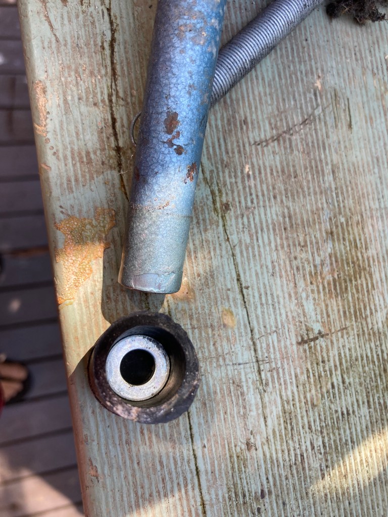
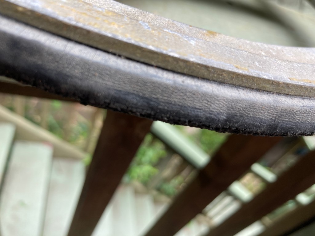
I am not too sure what to call this other than the sticky out metal bit welded onto the motor cradle. Its purpose is to stop the wide end of the cone going past the rubber on the drivewheel. This can cause damage to the rubber on the drivewheel and can also ‘lock’ into position and grind away. It should have a rubber shoe on it as pictured above. In side the shoe can be up to 4 or so small metal washers. These are there to fine tune the exact position that the cone stops at while on full speed. The way of testing is to turn the wheel on its side with the motor turned off. Gently push the pedal down all the way until it stops. Put your hand against where the cone and rubber meet and the sharp bottom edge of the cone should be just below the rubber ring.
The rubber boot is perishable and it is commonly seen missing in wheels that come to me for repairs. You may have noticed the small spring attacked to the sticky out metal bit and i will explain their purpose next.
Springs and things.
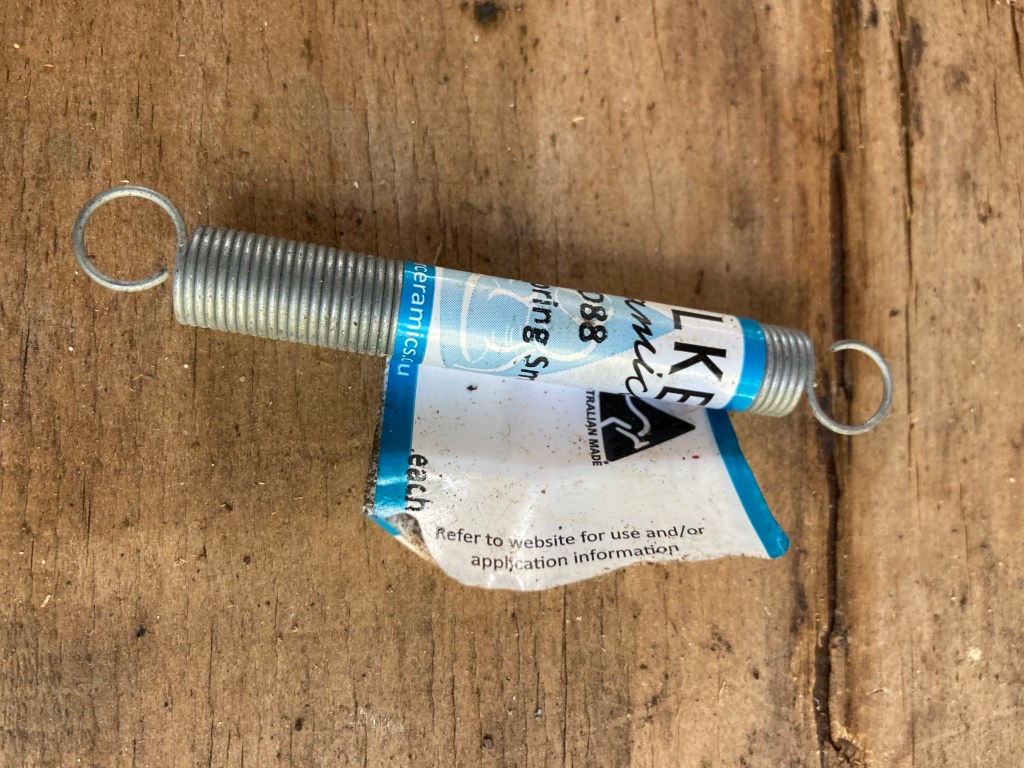
There are two springs in venco no3 and 5 wheels. The small one attaches to a small lug on the underside of the drip tray , the other end to the motor cradle. This spring maintains the correct pressure between the drivewheel rubber and cone so you get enough force to throw a decent amount of clay. Too much pressure would cause excess wear to the drivewheel so it’s important to only use springs supplied by venco. These are available from good pottery suppliers.
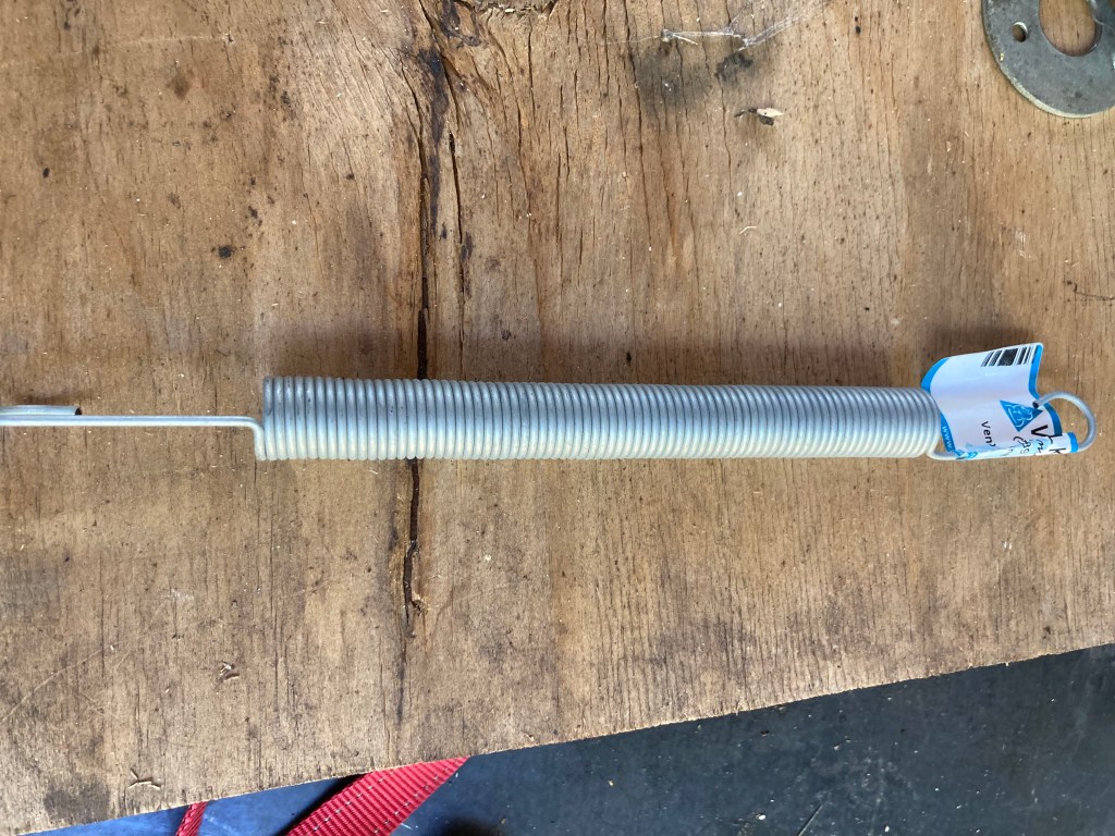
The large main spring is there to help with the amount of force needed to depress the foot pedal and get the wheel spinning. When in off position of the foot pedal the spring is stretched out in tension. When you press the pedal it helps lift the motor to engage the cone. Without it you would have to press very hard on the pedal to raise the motor and it would get very tiring quickly. The spring is always in tension so over time it looses its springiness and becomes ineffective. If you hold the spring up and give it a little shake and it feels all floppy then its time to change it. Generally speaking they are not expensive items and can make your wheel feel like new again.
External links and information on other wheel brands.
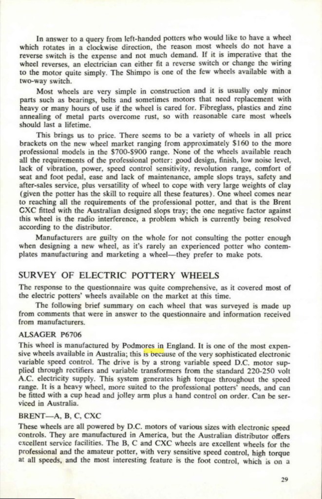
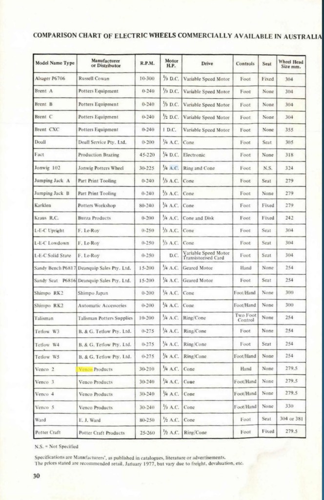
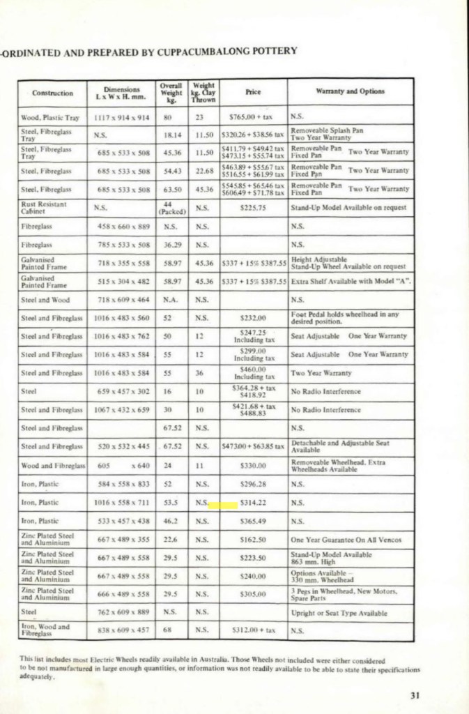
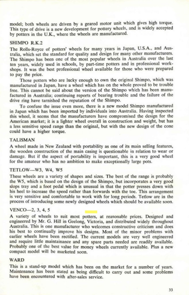
The following article was published in Pottery In Australia magazine Volume 16 No1 1977 by Doug Alexander. At the time of printing a Venco wheel costed around $225.


Contact and About Us
Blog by Peter Steggall. Thanks to anyone whose photos and videos I have used. If you have any problems with the use of your material please let me know.
Link to other posts on repairs to Venco wheels:
https://vencopotterywheels.wordpress.com/author/hugostiegl/
Facebook link. https://www.facebook.com/ceramicartcraft
Contact form.


